FAQ


Tempotech in detailsHave a Question ?
What is Thermocouple?
A Thermocouple is a temperature sensor, In Most Common form it consist of two wires of different alloys. The two different wires are welded together at 2 different points which have different temperatures.
One of the points is at known temperature . This point is reference junction. The reference junction is also called the “cold” junction. The temperature of the reference junction is held constant , or its variation is electronically compensated for in the associated measuring instrumentation.
The second junction is the measuring junction. The measuring junction is also often, but less preferably, called the “hot” junction. The measuring junction is often at an unknown temperature requiring measurement, or at a temperature at which control is required.
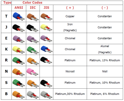
A thermocouple is useful for temperature sensing because a measurable electrical signal is produced. The signal is a function of the difference in temperature between the measuring and reference junctions. Numerous combinations of dissimilar metals are used as thermocouples. Some of these combinations have become relatively standard and widely accepted for a large segment of industrial temperature measurements. A specific combination is generally referred to as a type, or calibration. Most of the common calibrations have American National Standards Institute (ANSI) letter codes. These letter codes were originally established by the Instrument Society of America.
The recommended temperature range for each type is that for which limits of error are established. No guarantee is made, or implied, regarding the successful use of any of the above calibrations in their recommended range. Use of a thermocouple outside its recommended temperature range may adversely affect its reliability over its recommended
range.
Numerous factors combine to determine the successful application of a particular thermocouple. Some of these factors are temperature, cycling, chemical exposure, degree of protection provided, and mechanical abuse given to the thermocouple.
Thermocouple calibrations are maintained by proper manufacturing control of each of the thermoelements. Elemental constituents are controlled to a high degree. Homogeneity must be maintained, and all wire must be properly annealed.
What is Thermocouple Extension Wire?
To reduce costs when long thermocouple lengths are required, especially with the noble metal calibrations, extension leadwire extends the reference junction of the thermocouple to the instrument. For the base metal calibrations the extension wire is nominally of the same composition as the thermocouple grade material. Control in manufacturing is not to the same degree as thermocouple grade wire. With lessening rigidity of manufacturing control considerable expense can be saved. There is a limitation on the maximum temperature to which the junction of extension wire and thermocouple wire should be exposed. For the base metal calibration except Type T the maximum temperature is 400°F (204°C). For type T it is 200°F (93°C)
Noble metal types R, S, B, Platinel, the Tungsten-Rhenium calibrations are used with “compensating alternate” extension wire, which means the extension wire is made of material differing in composition from the thermocouple wire, but at temperatures encountered at the thermocouple extension junction, has corresponding temperature-EMF characteristics. The maximum temperature limitations for the thermocouple extension junction for calibration types R, S, B, and Platinel is 400°F (204°C). For Tungsten/Tungsten — 26% Rhenium (W/W — 26% Re), Tungsten — 3% Rhenium/Tungsten — 25% Rhenium (W — 3% Re/W – 25% Re) it is 500°F (260°C). For W- 5% Re/W- 26% Re it is 1600°F (871°C). The reason for the temperature limitation is that the thermocouple and extension wire junction is one of the materials of differing composition, and hence another thermocouple.
Whenever extension wire is used, precautions should be taken to insure a uniform temperature exists across both thermocouple and extension wire junctions. If there is sufficient temperature gradient between the temperature and extension wire junctions and the terminals at the instrument when copper extension wire is used, appreciable error may be produced.
Thermocouple extension wires should be installed in conduit whenever possible, and the conduit should be well grounded. Never run other electrical wires in the same conduit with extension wires. Keep the extension wires at least a foot away from any AC line
Thermocouple junction types and benefits
Grounded Junction: In grounded junction thermocouple wires and sheath of the mineral insulated cable is welded together to form a junction. Thermocouple wires and sheath becomes an integral part of the junction. Thus, the wire is grounded to the sheath.
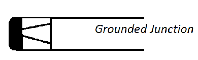
Key Benefits:
· Slower response than Exposed junction, but offers rugged construction.
· Can hold higher pressure than exposed junction and Ungrounded junction.
Ungrounded Junction: Junction is similar to grounded junction except wire are fuse welded, which is then insulated with Mgo powder and formed cap by welding without incorporating thermocouple wires. Thus, the junction is called the ungrounded junction.
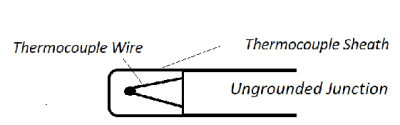
Key Benefits :
· Wires are protected from any mechanical damage
· Offers rugged construction, the same as the grounded junction.
· Strain due to differential expansion between wire and sheath is minimized with insulated wires.
Exposed Junction: In expose junction, the sheath is removed, and thermocouple wires fuse-welded to form a junction.
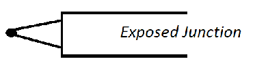
Key Benefits:
· Fast Response Time
Base Metal Thermocouple Types and Tolerance
| Type | Temperature | Standard Limit | Special Limit |
| T | -200 °C to 0 °C 0 °C to 350 °C | ± 1 °C or 1.5% Whichever is greater ± 1 °C or .75% Whichever is greater | N/A ± 0.5 °C or 0.4% Whichever is greater |
| J | 0 °C to 750 °C | ± 2.2 °C or .75% Whichever is greater | ± 1.1 °C or 0.4% Whichever is greater |
| E | -200 °C to 0 °C 0 °C to 900 °C | ± 1.7 °C or 1.0% Whichever is greater ± 1.7 °C or .5% Whichever is greater | N/A ± 1 °C or 0.4% Whichever is greater |
| K OR N | -200 °C to 0 °C 0 °C to 1250 °C | ± 2.2 °C or 2.0 % Whichever is greater ± 2.2 °C or .75% Whichever is greater | N/A ± 1.0 °C or 0.4% Whichever is greater |
ANSI ,IEC & JIS Thermocouple wire Insulation Color Coding & Magnet Check
What are the different types of thermocouples and their Temperatrue Range ?
Thermocouples have different temperature ranges depending on their type. Here’s an overview of the typical temperature ranges for various thermocouple types:
Type K -200°C to 1,260°C (-328°F to 2,300°F)
Type J (Iron-Constantan) -40°C to 750°C (-40°F to 1,382°F)
Type T (Copper-Constantan) -200°C to 350°C (-328°F to 662°F)
Type E (Chromel-Constantan) -200°C to 900°C (-328°F to 1,652°F)
Type N (Nicrosil-Nisil) 0°C to 1,700°C (32°F to 3,092°F)
Type S (Platinum-Platinum/Rhodium) 0°C to 1,760°C (32°F to 3,200°F)
Type B (Platinum/Rhodium-Platinum/Rhodium) 0°C to 1,820°C (32°F to 3,308°F)
Type C (W-Re) 0°C to 2,300°C (32°F to 4,172°F)
Type D (W/Re) 0°C to 2,200°C (32°F to 3,992°F)
How do thermocouples work?
Thermocouples are temperature sensors that work based on the principle of the Seebeck effect. When two dissimilar metal wires (such as copper and constantan) are joined at one end and exposed to a temperature difference, a small voltage is generated at the junction. This voltage is proportional to the temperature difference between the junction and the other ends of the wires. By measuring this voltage, the temperature can be determined. Thermocouples are commonly used in industrial applications due to their wide temperature range, durability, and simplicity. Different metal combinations are used for different temperature ranges and accuracy.
What is the accuracy of thermocouples?
Here’s a breakdown of Standard Limit and Special Limit accuracy for common thermocouple types, based on ANSI/ASTM E230 standards:
| Thermocouple Type | Standard Limit of Error (SLE) | Special Limit of Error (SLE) |
|---|---|---|
| Type K (Chromel/Alumel) | ±2.2°C or ±0.75% of reading (whichever is greater) | ±1.1°C or ±0.4% of reading (whichever is greater) |
| Type J (Iron/Constantan) | ±2.2°C or ±0.75% of reading (whichever is greater) | ±1.1°C or ±0.4% of reading (whichever is greater) |
| Type T (Copper/Constantan) | ±1.0°C or ±0.75% of reading (whichever is greater) | ±0.5°C or ±0.4% of reading (whichever is greater) |
| Type E (Chromel/Constantan) | ±1.0°C or ±0.5% of reading (whichever is greater) | ±0.5°C or ±0.3% of reading (whichever is greater) |
| Type N (Nicrosil/Nisil) | ±1.0°C or ±0.25% of reading (whichever is greater) | ±0.5°C or ±0.1% of reading (whichever is greater) |
| Type R (Platinum/Platinum-Rhodium) | ±1.5°C or ±0.25% of reading (whichever is greater) | ±0.5°C or ±0.1% of reading (whichever is greater) |
| Type S (Platinum/Platinum-Rhodium) | ±1.5°C or ±0.25% of reading (whichever is greater) | ±0.5°C or ±0.1% of reading (whichever is greater) |
Type K and Type N Thermocouple ?
Type K and Type N thermocouples are popular temperature sensors, but they have different characteristics, advantages, and limitations. Here’s a detailed comparison to help you understand the differences between the two and how to choose the best one for your specific application:
1. Materials
- Type K:
- Positive leg (Chromel): A nickel-chromium alloy.
- Negative leg (Alumel): A nickel-aluminum alloy.
- Type K is widely used due to its cost-effectiveness and versatility in many industrial applications.
- Type N:
- Positive leg (Nisil): A nickel-silicon alloy.
- Negative leg (Nisil): A nickel-silicon alloy.
- Type N thermocouples use a more stable alloy combination, which offers better performance in certain environments than Type K.
2. Temperature Range
- Type K:
- Temperature range: -200°C to +1372°C (-328°F to +2502°F).
- Type K is suitable for both low and very high-temperature applications.
- Type N:
- Temperature range: -200°C to +1300°C (-328°F to +2372°F).
- Type N has a slightly narrower temperature range than Type K but still covers a wide range for many industrial applications.
3. Accuracy
- Type K:
- Accuracy: Typically ±2.2°C or 0.75% of the reading (whichever is greater).
- Type K has lower accuracy, especially at higher temperatures, compared to some other thermocouples.
- Type N:
- Accuracy: Generally better than Type K, typically around ±1.0°C or 0.5% of the reading (whichever is greater).
- Type N is known for its better accuracy at high temperatures and overall better stability over time.
4. Stability and Durability
- Type K:
- Type K thermocouples are generally stable at lower to mid-range temperatures but can experience drift and degradation over time, especially at high temperatures (above 1000°C).
- The alumel leg can oxidize at high temperatures, affecting accuracy.
- Type N:
- Type N thermocouples are more stable than Type K, especially at high temperatures. The Nisil alloy is resistant to oxidation and offers better long-term stability, making it more reliable in extreme environments.
- Type N thermocouples are particularly known for their high-temperature stability and can last longer under harsh conditions, even in oxidizing environments.
Whats is a cold or reference junction for thermocouples ?
A cold junction (also known as a reference junction) is an essential concept in thermocouple temperature measurements. It refers to the part of the thermocouple circuit that is not exposed to the temperature being measured, typically the point where the thermocouple wires connect to the measurement device or instrumentation. This junction is at a known temperature and is crucial for accurate temperature readings.
Why is the Cold Junction Important?
When a thermocouple generates a voltage due to the temperature difference between the hot junction (where the temperature is being measured) and the cold junction, the voltage generated is directly proportional to the temperature difference between the two junctions.
Since thermocouples measure the difference in temperature between the hot junction (the measuring point) and the cold junction (the connection point), the voltage produced by the thermocouple depends on the temperature at both junctions. If the temperature at the cold junction changes, it will affect the voltage generated, leading to inaccurate readings unless corrected.
Why is there a difference between the temperature indicated by a thermocouple and the actual temperature ?
The difference between the temperature indicated by a thermocouple and the actual temperature is primarily due to several factors related to the thermocouple’s construction, measurement environment, and inherent properties. Here are the key reasons for such discrepancies:
- Manufacturing Tolerances
- Reference Junction (Cold Junction) Compensation
- Incorrect CJC Measurement
- Environmental Temperature Variations
- Material Characteristics
- Aging of the Thermocouple
- Thermal Drift
- Electromagnetic Interference (EMI)
- Thermocouple Placement
- Thermal Contact Resistance
- Heat Flow Variations
- Loose Connections